
ABOUT
Hanhai Opto-electronic is a major scientific research achievement transformation institution of the Hefei Institute of Physical Science, Chinese Academy of Sciences.
Hanhai Opto-electronic is a major scientific research achievement transformation institution of the Hefei Institute of Physical Science, Chinese Academy of Sciences.

Hanhai Optoelectronics centers on laser absorption spectroscopy-based gas detection (TDLAS)technology, developing and manufacturing a full range of products to deliver comprehensive gas detection solutions for cross-field and multi-industry customers.

Hanhai Optoelectronics' laser gas detection products focus on the monitoring of flammable, explosive, toxic and harmful gases as well as greenhouse gases. Leveraging mature technical solutions and flexible product adaptability, these products can be widel

With over a decade of technical accumulation and recognition from nearly a hundred customers, Hanhai Optoelectronics' laser gas detection products have delivered successful cases covering core scenarios across petrochemicals, urban gas, environmental moni

The company's core technology has been jointly recommended by the Ministry of Emergency Management, the Ministry of Science and Technology, and the Ministry of Industry and Information Technology.
I. Project Background and Pain Point Analysis
1.1 Policy-driven Requirements
In accordance with Requirements for Work Safety Standardization Management System of Large and Medium-sized Enterprises (GB/T33000-2025) implemented on October 31, 2025, enterprises are required to promote advanced technical equipment, reduce manual inspection and manual operations, establish safety risk monitoring and early warning systems, and achieve real-time monitoring and proactive early warning. As high-risk facilities, buried gas pipelines are in urgent need of monitoring solutions that meet standardized requirements to support their safety management.
1.2 Industry Status Quo and Pain Points
Current leakage detection technologies for long-distance buried gas transmission pipelines have obvious shortcomings and are difficult to meet the core demand for real-time online monitoring. The specific problems are as follows:
Traditional flaw detection method: Only applicable for internal pipeline inspection, it has high requirements for pipeline conditions, is prone to accidents such as blockage and shutdown, and cannot realize online monitoring, resulting in insufficient timeliness and stability.
Operational parameter external detection method: Although detection methods based on parameters such as pressure, flow rate, and vibration can achieve continuous monitoring, they have low positioning accuracy and high false alarm rates, leading to poor practicality in engineering applications.
Manual inspection-assisted method: Relying on portable devices, vehicle-mounted detectors, or trained animals, it cannot guarantee the timeliness of detection and significantly increases personnel costs.
Core common problems: Buried pipelines have no power supply conditions, detector maintenance is difficult, and the service life of detectors needs to match that of pipelines. Existing technologies fail to meet these core conditions simultaneously, resulting in the long-term inability to achieve real-time online monitoring.
II. Solution Objectives
With the passive laser online monitoring system as the core and combined with Tunable Diode Laser Absorption Spectroscopy (TDLAS) technology, this solution aims to achieve the full-life-cycle safety monitoring of buried pipelines. The specific objectives are as follows:
Break through the restriction of no power supply in buried environments, realize 24/7 real-time online monitoring, and eliminate the need for on-site manual inspection.
Enhance monitoring accuracy to enable early warning of trace methane leaks, featuring precise positioning and low false alarm rates.
Simplify system maintenance, realize detector operation with no calibration required and long service life, and reduce the whole-life-cycle cost.
Build an integrated monitoring platform to realize functions such as real-time data upload, trend analysis, and hierarchical alarm, meeting the requirements of management informatization.
Adapt to buried pipelines of different diameters and lengths, ensuring flexible installation, convenient construction, and no impact on the surrounding environment.
III. Core Technology and System Design
3.1 Core Technical Principle
The Tunable Diode Laser Absorption Spectroscopy (TDLAS) technology is adopted, which is based on the Lambert-Beer Law: specific gas molecules have exclusive absorption characteristics for laser of specific wavelengths, and the laser attenuation degree has a stable proportional relationship with gas concentration. For example, methane (CH₄) only absorbs laser with a wavelength of 1654nm. By accurately emitting laser of this wavelength, specific monitoring of methane can be achieved without interference from other gases, temperature, or humidity.
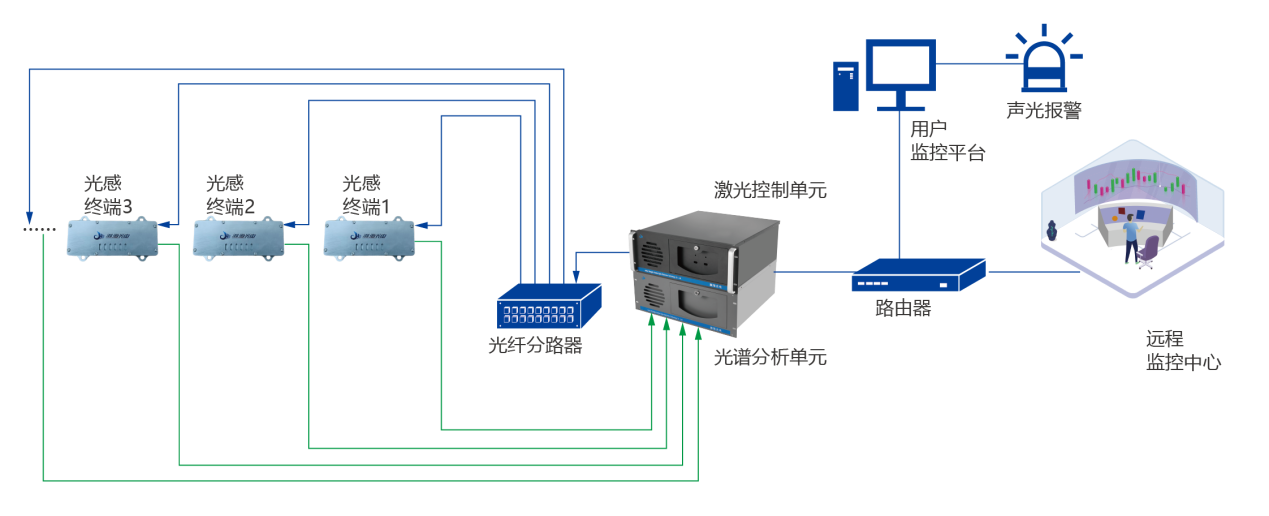
3.2 Overall System Architecture
The passive laser online monitoring system consists of three parts: the active unit, the passive unit, and the transmission medium. The architecture design is as follows:
Active unit: Comprising the laser control unit, spectral analysis unit, and monitoring platform, it is deployed in stations or monitoring centers with power supply conditions, and is responsible for laser emission, signal processing, and data display.
Passive unit: Also known as the optical sensing terminal (laser detector), it is made of optical glass and stainless steel without electronic components. Buried together with pipelines, it is responsible for on-site gas signal collection.
Transmission medium: Optical fibers are used to connect the active and passive units, with a laser transmission distance of over 20km, enabling remote separated operation.
Working Process: The laser control unit transmits detection laser to the optical sensing terminal via optical fibers. After the laser contacts the on-site gas, a characteristic attenuation signal is generated, which is then transmitted back to the spectral analysis unit via optical fibers. The gas concentration is calculated through signal processing, and finally uploaded to the monitoring platform to realize real-time monitoring and alarm.
3.3 Core System Advantages
Intrinsic safety: Passive design on site requires no power supply, avoiding electrical safety hazards.
High accuracy and reliability: Fingerprint-based detection with strong anti-interference capability and low false alarm rate, capable of monitoring ppm-level trace gas leakage.
Maintenance-free and long service life: The optical sensing terminal has no wear and tear, requires no calibration, and has a service life longer than that of pipelines.
Flexible adaptability: Supporting 1–128 monitoring channels, the spacing can be designed on demand to adapt to pipelines of different diameters.
Cost-effective: Significantly reducing the costs of manual inspection and later maintenance, it has high cost performance throughout the whole life cycle.
IV. Implementation Plan and Construction Specifications
4.1 Construction Process
Preliminary survey: Investigate the pipeline route, diameter, burial depth, and surrounding environment, determine the layout density of optical sensing terminals (recommended 4–5 units per kilometer with a spacing of 200–250 meters) and the installation location of the active unit.
Equipment prefabrication: Prefabricate supporting materials such as vent pipes, protective boxes, and optical fiber patch cords according to the survey results to ensure matching with the pipeline construction schedule.
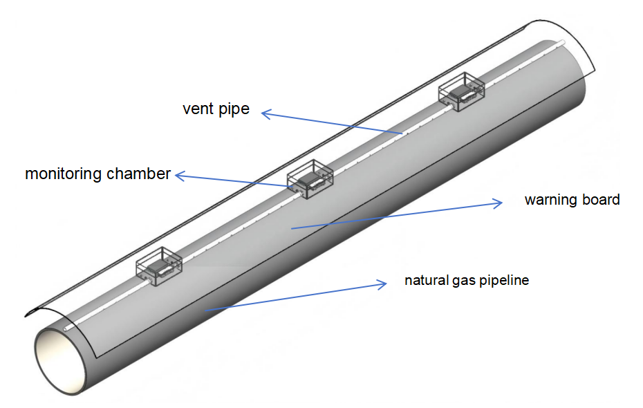
Synchronous construction: During pipeline laying, install the optical sensing terminals and vent pipes synchronously. The optical sensing terminals are placed in monitoring chambers, which are connected to the vent pipes.
Construction of Ventilation Corridor: Lay airtight warning plates (molded PE polymer) over the ventilation pipes to form a closed ventilation corridor, guiding the leaked gas to gather toward the optical sensing terminals.
Optical fiber laying and connection: Lay armored optical fibers along the pipeline route, connect the optical sensing terminals with the active unit in the monitoring center, and complete the waterproof and pressure-resistant treatment of optical fiber splice closures.
4.2 Key Construction Requirements
The vent pipes adopt Φ20 specification and are fully covered with capillary holes to ensure smooth gas entry.
The width of the warning plate shall be slightly larger than the diameter of the pipeline; it shall be laid closely above the vent pipe to block gas diffusion.
3M waterproof and pressure-resistant optical fiber splice closures are adopted to avoid damage to interfaces caused by underground moisture and pressure.
Avoid damaging the original pipeline structure during construction. Backfill soil should be compacted in layers without affecting pipeline stability.

Vent Pipe
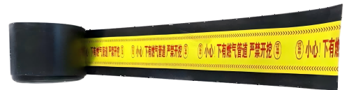
Warning Board
V. Application Scenarios and Case Verification
5.1 Applicable Scenarios
This solution is applicable to the monitoring of all types of buried gas pipelines, including methane leakage detection for long-distance natural gas pipelines, urban natural gas pipe networks and LNG receiving terminals.
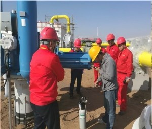
5.2 Typical Case Verification
Case 1: Shanjing IV Pipeline Project of PipeChina
China National Pipe Network Group applied our company’s Passive Laser Online Monitoring System to the Shanjing IV Trunk Pipeline — the pipeline with the largest diameter and highest pressure in China at that time — and constructed the world’s first online monitoring network for long-distance buried pipelines. This system is mainly designed for 24/7 real-time online monitoring of buried pipelines and insulating joints along the Shanjing IV Pipeline. It has fundamentally resolved the long-standing challenge of being unable to detect leaks in buried pipelines, and enabled real-time online leak monitoring in enclosed spaces traversed by natural gas pipelines without any external power supply.
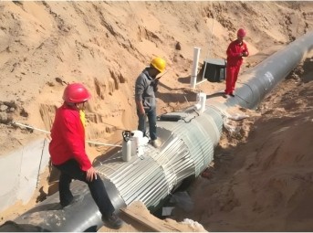
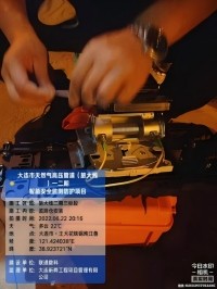
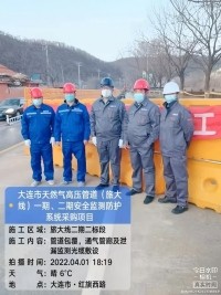
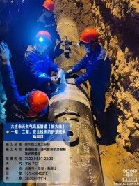
Case 2: Phase II Project of Dalian Natural Gas Pipeline (Lvda Line)
As a critical regional energy supply infrastructure, the Phase II Project of Dalian Natural Gas Pipeline (Lvda Line) stretches a total length of 36.75 km and undertakes the task of transporting high-pressure natural gas. To address the leakage risks in high-consequence areas of buried pipelines caused by geological subsidence, corrosion and other hazards, and ensure the safe and stable operation of the pipeline, the project adopted the Passive Laser Online Monitoring System for full-scale leakage monitoring. By deploying passive optical sensing terminals at leakage-prone points such as pipeline insulating joints, the system relies on optical fiber transmission to detect laser signals, enabling it to accurately capture ppm-level micro-leaks and quickly locate the leak points. Compared with traditional methods such as manual patrols and pressure monitoring, it boasts distinct advantages including high real-time performance, superior detection accuracy, no requirement for on-site power supply and low operation and maintenance costs. It achieves all-weather monitoring of buried pipelines, effectively preventing leakage accidents, safeguarding the lives and property of residents along the pipeline route and maintaining the stability of regional energy supply. It also sets a high-quality technical benchmark for the safety monitoring of long-distance buried natural gas pipelines.
VI. Solution Value Summary
Through the innovative application of passive laser online monitoring technology, this solution completely solves the monitoring pain points of buried pipelines such as no power supply, difficult maintenance, and the need for long service life, achieving the safety management goals of "real-time monitoring, accurate early warning, maintenance-free operation, and low cost". Complying with the national work safety standardization requirements, the solution reaches the leading domestic and advanced international technical level, providing reliable guarantee for the full-life-cycle safety of buried pipelines. Meanwhile, it significantly reduces the enterprise's safety prevention and control as well as operation and maintenance costs, delivering remarkable economic and social benefits.
TEL:400-055-1239 (9:00~17:00)
MAIL:lisghanhai@gkhhlaser.com
ADDR:302 Floor, Building 5, No. 18, Kechuang 13th Street, Beijing Economic and Technological Development Zone